Working Principle Of Electromagnetic Flow Meters
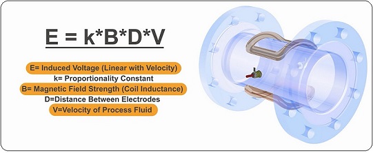
Electromagnetic Flow Meters are based on FARADAY’S LAW INDUCTION. These meters are also called as Magnetic or Electromagnetic Flow Meters. A magnetic field is applied to the metering tube, which results in a potential difference proportional to the flow velocity perpendicular to the flux lines. The physical principle at work is electromagnetic induction and mathematically,
defined as, E=k*B*D*V
where,
- E=Induced Voltage (Linear with velocity).
- k=Proportionality Constant.
- B=Magnetic Field Strength (Coil Inductance).
- D=Distance between electrodes.
- V=Velocity of process fluids.

The induced voltage (E) is directly proportional to the velocity (V) of the fluid moving through the magnetic field (B). The induced voltage is carried to the transmitter through the electrode circuit. The transmitter then converts this voltage into a quantifiable flow velocity. The volumetric flow rate of the fluid is calculated using this known velocity along with the area of the pipe.
When a flow meter is installed and activated, its operations begin with a pair of charged magnetic coils. As energy passes through the coils, they produce a magnetic field that remains perpendicular to both the conductive fluid being measured and the axis of the electrodes taking measurements. The fluid moves along the longitudinal axis of the flow meter, making any generated induced voltage perpendicular to the field and the fluid velocity. An increase in the flow rate of the conductive fluid will create a proportionate increase in the voltage level.
The meter features flanged construction and is available with a choice of liner and electrode material. All meters consist of a sensor and a converter that may be mounted integral to the sensor or remotely either with a field mount kit.


