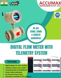
Telemetry Flow meters complied with CGWA guidelines monitor the ground water extraction and provide the data directly to the authority.
The data collection process is:
- Install Electromagnetic flow meter
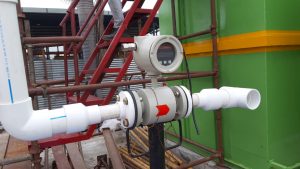
The electromagnetic flow meter will be installed at the water discharge point on borewell. The meter will record the flow of the water extracted from the ground / borewell.
- IoT Device
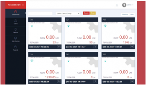
IoT device is a secured gateway connecting flow meter data to cloud server. It will transmit data at regular basis and allows the user to download its accurate flow statistics. Every meter will have unique dashboard display with features like flow rate and pump hour report. It also facilitates to download auto-generated reports at regular intervals.
Accumax Electromagnetic Flow meter appearance on dashboard:

According to CGWA guidelines, if an industry is extracting water from the ground in excess amount, it is bound to inform the same to the authority. Later the authority will provide NOC taking into consideration the water requirement of the industry. Once the NOC is issued the industry should install the flow meter and Piezometer (if mentioned) meeting the specifications of the governing body.
The installation of a telemetry flow meter should be regulated in the following manner:
- The meter shall be installed at the discharge point at the bore well before branching.
- No bypassing of pipe is allowed before the installed flow meter.
- The pipe must have a full bore pass all the time so no air can pass through it manipulating the flow measurement.
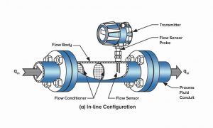
- Sufficient upstream and downstream space shall be provided for the proper installation of the meter.
- In case there is no full bore pass of water, the meter shall be installed in the U-band position as shown below.

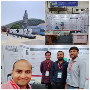
GPBS Exhibition 2022
Stall no:- E- 76
Sarsana Convention Center, Surat.

According to the notice issued by the Authority on 08.01.2021, all the industries extracting water from ground, except exempted categories, should install flow meters meeting CGWA guidelines having Telemetry system, or they will be liable for penalty. The industries should install the meters and confirm it with the CGWA about installation within 30 days from the date of NOC issued to them.
The flow meters shall meet below specifications as per the guidelines:
The flow meter shall be either Electromagnetic flow meter of Ultrasonic meter.
The meter shall be either battery operated or power should be supplied through UPS.
The meter shall be as per ISO 4064:2014 Standards having flow range accuracy better than +2.
The meter and telemetry system should be sealed in a way that any attempt to open the system breaks the tag.
The manufacturer shall submit latest NABL / FCRI / NPL certificate for every meter.
The telemetry system shall record the flow data directly to the cloud server that is further empaneled with The Ministry of Electronics and Information Technology.
The meter shall transmit following parameters to the server


As the world is facing shortage of natural resources due to excess and irregular consumption, the Government is stepping forward to preserve the same. There is an excessive usage of water by the industrial premises. To control the wastage and have the accurate record of consumed water, the Ministry of Jal Shakti formed Central Ground Water Authority (CGWA) under Environmental Protection Act.
The functions of the CGWA statutory body are to issue NOC to various industrial and mining projects for extracting the water from the ground in prior. It states the technical specifications for water meter based on the consumption of industry.
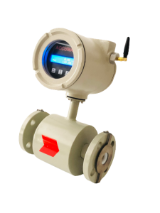
Accumax offers Digital water flow meter as per CGWA guidelines:

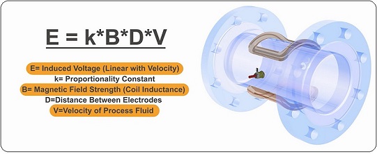
The design of the magnetic flow meter is such that the area having direct contact with the water withstands the corrosion. The inside body is made up of polytetrafluoroethylene (PTFE) liner and Stainless Steel electrodes. The straight structured flow design increases the accuracy of the flow measurement and identifies the pressure drop in the same. It is used to measure liquids like water, wastewater, slurries, and other corrosive liquids. The conductivity of the liquid should be equal to or more than 10 micro siemens/cm. The advanced flow meter can measure the flow of liquid from both directions – forward and backward. The low flow range will show less accuracy in large-sized flow meters compared to a small-sized flow meter. Generally, the accuracy remains at 0.5% of full scale.

Flow meters are widely applicable to track the volume of fluid, gas or steam in industries as
- Effluent Treatment Plants (ETP)
- Pharmaceutical
- Pulp & Paper
- Food & Sugar
- Automation & Process industries
- R.O plants
- Textile
- Sewage Treatment Plant (STP)
- Chemical
- Mining
- Ceramic
- Beverage
- Steel
- Agriculture
They are also helpful to maintain standard quality of the product by accurate measurements.


Flow meter devices are used to measure the volume and velocity of fluids, steam or gas flowing through pipes. These meters are also named as – digital water meter, flow indicator, flow sensor, flow gauge, telemetry meters, magnetic flow meters, liquid meter, gas meter, etc. They measure the flow at bore well, streams, rivers, water or oil tanks, gas stations, etc. They also add green values to the environment preserving resources.
The choice of flow meter depends on the nature of liquid passing through pipes. Flow meters are highly accurate with long life span and low maintenance. They can measure the flow easily in all directions- forward, reverse, upward and downward. Digital flow meters track the real time flow enhancing accuracy.
