
When a Modbus RS485 link fails, the symptom is usually the same: the SCADA or PLC shows "timeout" and no data. The causes, however, range from a swapped wire to a misconfigured parity setting. A systematic approach finds the fault faster than random changes.
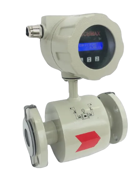
This guide applies to flow meters and controllers in general, including Accumax devices such as the electromagnetic flow meter, which offers RS485 with Modbus at baud rates from 2400 to 38400. Always check your device manual for register maps and defaults.
How the link works
RS485 is a differential two-wire bus. One master polls multiple slaves, each with a unique address. The master sends a request, the addressed slave replies, and everyone else stays silent. Communication works only if both ends agree on:
- Baud rate (for these meters, 2400 to 38400)
- Parity and stop bits
- Slave address
- Register address, function code and data type
A mismatch in any of these gives no reply or an exception response.
Step 1: Separate physical from logical faults
Ask first: is the problem electrical or configuration?
- If no device ever responds, suspect wiring, polarity, termination or master settings.
- If some respond and others not, suspect addresses, a break in the daisy chain or load.
- If it works then fails intermittently, suspect noise, grounding, termination or power quality.
- If it responds but values are wrong, suspect register mapping, byte order or scaling.
Step 2: Check the physical layer
- A/B polarity. Labelling differs between manufacturers; A and B (or D+ and D−) are sometimes reversed. After isolating power and following the wiring instructions, verify polarity against both manufacturers’ documentation before correcting the pair.
- Common reference. Connect the signal ground or shield reference as the manual recommends, so that receivers stay within common-mode range.
- Topology. Use a daisy chain, not a star. Stubs should be as short as possible.
- Cable. Use shielded twisted pair, preferably with the characteristic impedance suited to RS485. Do not use two random cores from a multi-core power cable.
- Shield. Earth at one end only to avoid ground loops, unless the system design says otherwise.
- Termination. Place a resistor, commonly 120 Ω, at each physical end of the bus only. Too many terminators overload the bus; none can cause reflections on long runs at high baud.
- Biasing. An idle bus needs defined levels. Typically one point provides bias resistors; check whether your converter already does.
Step 3: Check the configuration
| Setting | What to verify |
|---|---|
| Baud rate | Same on master and every slave (2400-38400 on Accumax meters) |
| Parity / stop bits | Match exactly, such as 8N1 versus 8E1 |
| Slave address | Unique on the bus, within the valid range |
| Function code | Reading holding versus input registers |
| Register offset | Some tools start at 0 and others at 1 |
| Byte/word order | Floating point values may be swapped |
Many "wrong value" faults are just word-order issues: a 32-bit float returned as two 16-bit registers, read in the opposite order, produces nonsense. Try the alternative order.
Step 4: Use the right tools
- A USB-RS485 adapter and a Modbus master tool on a laptop, connected directly to one device, quickly isolates the field wiring from the SCADA.
- A multimeter shows idle bus voltage; a healthy idle differential is generally a few hundred millivolts or more with biasing, but check the transceiver datasheet.
- An oscilloscope shows reflections, ringing and noise.
- A bus monitor or sniffer shows whether requests reach the device and whether replies are corrupted.
Test method: disconnect everything except one meter, set a low baud rate, such as 9600, poll that device. If it works, add devices back one at a time.
Step 5: Common fault patterns
Everything times out after commissioning
Usually polarity, wrong baud rate, or the master port pointing to the wrong COM port or gateway.
Works for hours, then drops
Look for noise from variable frequency drives, loose terminals, or a missing shield connection. Separate RS485 cables from motor cables by a decent distance, and cross them at right angles.
One device is flaky
Suspect its address clash, a poor terminal, or a device located on a long stub. Swap the cable section to test.
CRC errors
Cyclic redundancy check failures point to corrupted frames: noise, wrong parity or a baud rate close but not identical.
Slow responses and timeouts
The master's timeout may be too short for the slave or gateway; also check polling that is too fast for many devices. Increase the timeout and the inter-poll delay.
Step 6: Fix it for the long run
- Label every address and record settings in a commissioning sheet.
- Assess suitable surge protection and isolated converters where lines run between buildings, because lightning and ground potential differences damage ports.
- Keep the bus within sensible length for the baud rate; lowering baud rate often helps long runs.
- Document the register map; keep a copy of manuals in your downloads folder or document system.
- When integrating into SCADA, see Industry 4.0 and SCADA solutions and consider an IoT device as a gateway.
Troubleshooting also helps when the flow reading itself looks wrong; if communication is fine but values bounce, see diagnosing unstable flow readings.
Frequently asked questions
What baud rate should I use on the Accumax electromagnetic flow meter?
Modbus RS485 supports baud rates from 2400 to 38400. Choose a rate every device on the bus supports; 9600 is a common starting point for troubleshooting, and lower rates tolerate long cables better.
Do I always need a termination resistor?
Not always. Short runs at low baud rates often work without one, but for long cables or higher speeds, terminate both physical ends of the bus.
Can two devices share a Modbus address?
No. Each slave on the same bus needs a unique address, or replies will collide and produce garbled data.
Conclusion
Treat Modbus faults in layers: wiring, then communication settings, then register interpretation. Isolate one device, confirm it with a laptop, then rebuild the network step by step. Good cabling and a clear commissioning record prevent most problems.
Need help integrating our meters with your PLC or SCADA? Contact Accumax.
Written by the Accumax Engineering Team
The people who design, build and calibrate Accumax instruments in Gandhinagar since 1992.