Reliable instrumentation starts with a clearly defined measurement task. For ultrasonic level transmitter vs digital water level recorder, the important question is not simply which device to buy, but what decision its information will support. A maintenance team, a process operator and an environmental reporting team may need different records from the same installation. Agreeing those needs early prevents avoidable site changes later.
ACCUMAX INSTRUMENTS PVT LTD in Gandhinagar, India, works across flow measurement, controllers, level measurement, pH analysis and industrial IoT. This guide sets out a practical engineering approach without assuming that every product configuration includes the same interfaces, accessories or software functions.
Understand the measurement and its boundaries
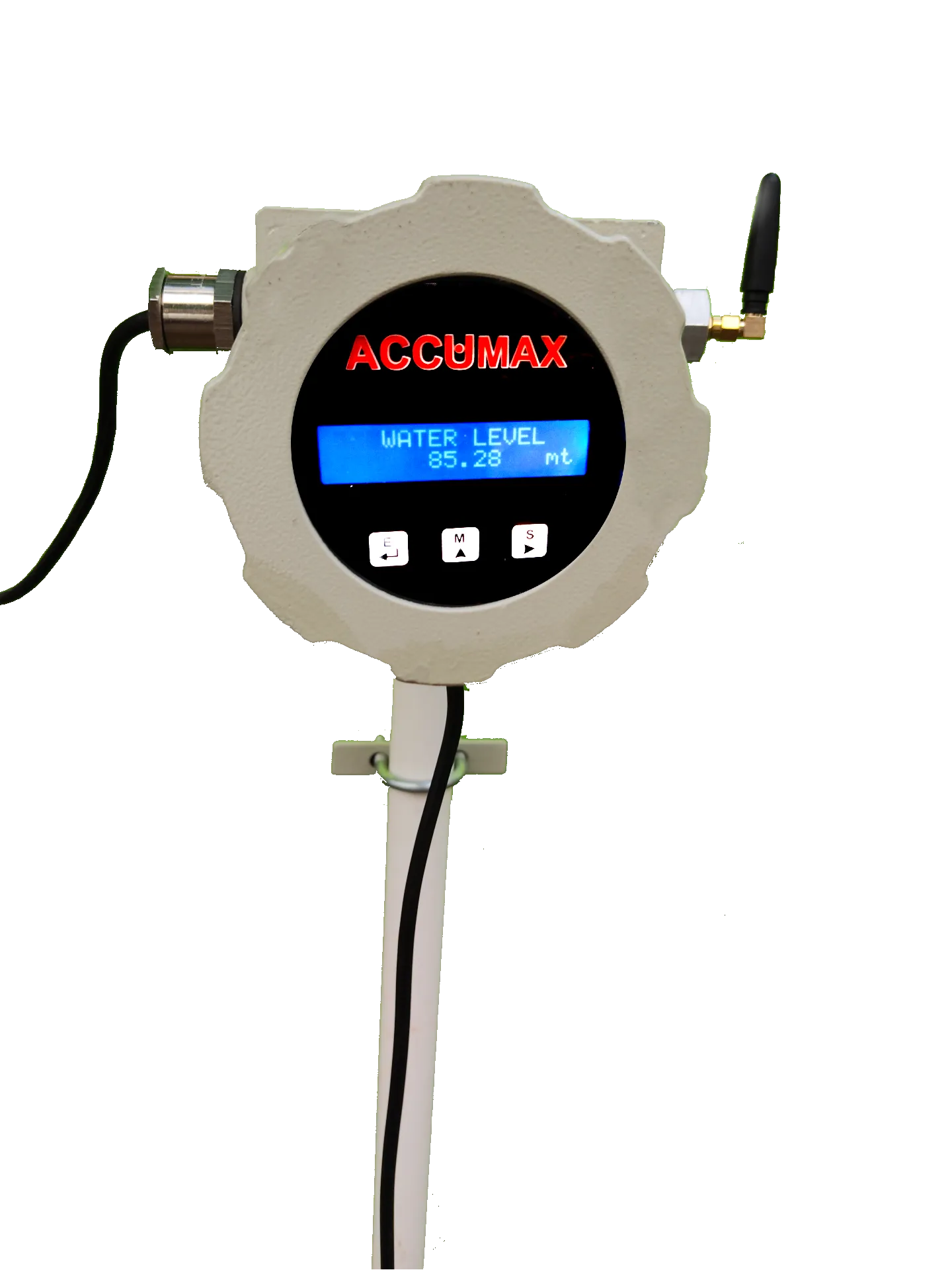
An ultrasonic level transmitter measures distance using an acoustic echo, normally from above the liquid. A digital water level recorder describes a recording function and may use a submerged pressure sensor. The terms are not equivalent sensor categories.
Start by drawing the physical system and the information path. Mark where the measurement originates, where it is converted, and where an operator sees it. Include power supplies and communication equipment because a healthy sensor cannot compensate for an unavailable gateway or a failed supply. This sketch also helps separate a measurement fault from a missing record.
Use the relevant ultrasonic level transmitter vs digital water level recorder product information as a starting point, then obtain the current configuration documents. Confirm the proposed hardware, installation limitations and accessories against the actual application rather than inferring capability from a product family name.
Define the application before selection
Use non-contact measurement where the surface can return a reliable echo and the mounting geometry avoids obstructions. For narrow monitoring bores, assess a suitable pressure-based recorder and its compensation method.
Create a short application sheet containing normal operation, credible extremes and maintenance conditions. A system selected only for its normal operating point may fail during startup, cleaning, seasonal change or an extended shutdown. Record uncertainties explicitly so they can be resolved during the site survey rather than hidden inside a purchase description.
The following checklist should be discussed with both operations and maintenance:
- Measurement geometry: identify the responsible person, the available evidence and the acceptance check before ordering.
- Foam and condensation: identify the responsible person, the available evidence and the acceptance check before ordering.
- Required record history: identify the responsible person, the available evidence and the acceptance check before ordering.
- Access for reference checks: identify the responsible person, the available evidence and the acceptance check before ordering.
Also record environmental exposure, access constraints and the available power arrangement. Confirm any required ingress protection or hazardous-area suitability for the specific equipment supplied; a generic product description is not evidence of approval for a particular location.
Installation and commissioning sequence
Establish a dependable reference
A reference is essential for distinguishing a configuration error from a real change. Depending on the application, it may be a manual measurement, a controlled functional test or an independently checked process observation. Record the method and its limitations. Do not compare two readings taken under different operating conditions and assume the difference is instrument error.
Install for serviceability
Keep terminals accessible, label cables at both ends and leave enough working space for safe replacement. Route signal wiring separately from high-current conductors where practicable. Follow the equipment instructions for shielding, grounding and mechanical support rather than applying one wiring rule indiscriminately to every interface.
Photograph the completed installation and record configuration values before closing enclosures. This simple step helps the next technician identify changes after a repair. Keep current manuals and configuration records with the plant documentation; the downloads area is a useful place to begin locating product literature.
Test the complete chain
Check the local result, transmitted value and stored record together. Confirm units, decimal positions, timestamps and alarm descriptions. An end-to-end test is stronger evidence than a successful connection alone. Include an approved abnormal-condition test so the team knows what happens when a signal or supply disappears.
Troubleshooting without masking the cause
Check the physical distance against the reported level before changing scaling. With pressure measurement, verify the sensor reference depth; with ultrasound, inspect echo obstructions and the specified blanking zone.
Use a staged investigation rather than changing several settings at once:
- Confirm whether the physical process actually changed.
- Compare the local indication with the receiving system.
- Inspect installation condition, power and accessible connections.
- Check configuration against the approved record.
- Repeat the reference check after each justified correction.
Retain the original observations and note the exact time of each intervention. If a problem appears only during pump starts, maintenance activities or communication sessions, that timing is useful evidence. Averaging, resets and repeated recalibration can temporarily hide symptoms while removing the clues needed to identify their origin.
Records, integration and operational responsibility
Where remote records are required, define the logging interval, transmission interval and expected recovery after a communication outage separately. A locally stored measurement and a delivered message are different outcomes. Confirm buffering and recovery behaviour for the selected equipment rather than assuming interrupted data will automatically reappear.
For integration planning, review the Industry 4.0 and SCADA solution. Access control, documented changes and network separation matter even on a small installation. Remote visibility should not create an undocumented path for changing critical settings or bypassing local protective functions.
If records support an external submission, establish the applicable requirements with the responsible authority or qualified adviser. Instruments can support evidence collection, but an instrument, telemetry service or dashboard never guarantees regulatory compliance. Keep installation, maintenance and verification evidence alongside the numerical records.
Frequently asked questions
Can both devices provide remote records?
Yes, if the selected transmitter or recorder has a compatible output and suitable logging or telemetry hardware. Confirm those capabilities for the actual configuration.
What should be included in the handover record?
Include equipment identity, configuration, installation reference information, wiring details, test results and the people responsible for maintenance. Record unresolved limitations as well as successful checks. A short, accurate handover is more useful than a large folder that omits the values actually loaded into the device.
How often should performance be checked?
Base the interval on process criticality, environmental exposure, operating history and the manufacturer’s guidance. Increase attention after repairs, unusual events or unexplained disagreement with a reference. Do not adopt a universal interval without considering the consequences of an undetected fault.
Conclusion
Ultrasonic Level Transmitter vs Digital Water Level Recorder requires a coherent approach to application definition, installation, verification and ongoing responsibility. Select against actual operating conditions, test the complete information chain and preserve enough context to explain unusual results. These practices make measurements more useful and reduce the chance that a small installation error becomes a recurring operational problem.
Contact Accumax to discuss your application and the configuration details needed for a practical proposal.
Written by the Accumax Engineering Team
The people who design, build and calibrate Accumax instruments in Gandhinagar since 1992.