Working Principle Of Electromagnetic Flow Meters

Electromagnetic Flow Meters are based on FARADAY’S LAW INDUCTION. These meters are also called as Magnetic or Electromagnetic Flow Meters. A magnetic field is applied to the metering tube, which results in a potential difference proportional to the flow velocity perpendicular to the flux lines. The physical principle at work is electromagnetic induction and mathematically,

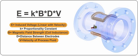
defined as,   E=k*B*D*V

where,

  • E=Induced Voltage (Linear with velocity).
  • k=Proportionality Constant.
  • B=Magnetic Field Strength (Coil Inductance).
  • D=Distance between electrodes.
  • V=Velocity of process fluids.

The induced voltage (E) is directly proportional to the velocity (V) of the fluid moving through the magnetic field (B). The induced voltage is carried to the transmitter through the electrode circuit. The transmitter then converts this voltage into a quantifiable flow velocity. The volumetric flow rate of the fluid is calculated using this known velocity along with the area of the pipe.

When a flow meter is installed and activated, its operations begin with a pair of charged magnetic coils. As energy passes through the coils, they produce a magnetic field that remains perpendicular to both the conductive fluid being measured and the axis of the electrodes taking measurements. The fluid moves along the longitudinal axis of the flow meter, making any generated induced voltage perpendicular to the field and the fluid velocity. An increase in the flow rate of the conductive fluid will create a proportionate increase in the voltage level.

The meter features flanged construction and is available with a choice of liner and electrode material. All meters consist of a sensor and a converter that may be mounted integral to the sensor or remotely either with a field mount kit.

Why Electromagnetic Flow Meter

Electromagnetic Flow Meters represent about 24% of all flow meters sold today.  Applications for dirty liquids are found in the water, wastewater, mining, mineral processing, power, pulp and paper, and chemical industries. Water and wastewater applications include custody transfer of liquids in force mains between water/wastewater districts. Magnetic flow meters are used in water treatment plants to measure treated and untreated sewage, process water, water, and chemicals. Mining and mineral process industry applications include process water and process slurry flows and heavy media flows.

With proper attention to materials of construction, the flow of highly corrosive liquids (such as acid and caustic) and abrasive slurries can be measured. Corrosive liquid applications are commonly found in chemical industry processes and in chemical feed systems used in most industries. Slurry applications are commonly found in the mining, mineral processing, pulp and paper, and wastewater industries.

All measurement principles have their strengths and weakness, which determine when they are the best option.


PROS

  1. The obstruction to the flow is almost nil and therefore this type of meters can be used for measuring heavy suspensions, including mud, sewage and wood pulp.No pressure loss.
  2. They are practically unaffected by variation in density, viscosity, pressure and temperature.
  3. There is no pressure head loss in this type of flow meter other than that of the length of straight pipe which the meter occupies..
  4. They are not very much affected by upstream flow disturbances.Less maintenance.
  5. The meters are suitable for most acids, bases, water and aqueous solutions because the lining materials selected are not only good electrical insulators but also are corrosion resistant.


CONS

  1. Electrical Conductivity of the liquid media required should be equal to or more than 5μS/cm.
  2. Incrustation can cause errors.
  3. Only effective on conductive fluids and materials such as unmixed hydrocarbons and gases cannot be measured.
  4. As the meter always measures the volume rate, the volume of any suspended matter in the liquid will be included.
  5. To avoid any trouble which would be caused by entrained air, when the flow tube is installed in a horizontal pipe-line, the electrodes should be on the horizontal diameter.
  6. To avoid any trouble which would be caused by entrained air, when the flow tube is installed in a horizontal pipe-line, the electrodes should be on the horizontal diameter.
loading
WhatsApp chat
Share this Page whatsapp