Industrial IoT
Data Logger for Flow Meter
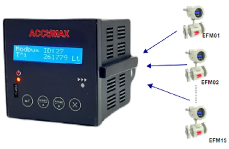
The Accumax Data Logger for Flow Meter records flow rate and totalizer data from up to 15 flow meters simultaneously over a Modbus RS485 connection. Data is written to a memory card in an Excel-compatible format, so records can be pulled straight into a spreadsheet for analysis and reporting without manual data entry.
Features
-
Logs up to 15 flow meters simultaneously
A single logger can record data from as many as 15 flow meters at the same time.
-
Modbus RS485 connection
Connects to flow meters using the RS-485 protocol for data storage, giving compatibility with a wide range of devices.
-
Excel-compatible storage
Data is stored in Excel format on a memory card for easy access and analysis.
-
Collective live totalizer view
Live totalizer data from all connected flow meters can be accessed in one place.
-
Records flow rate and totalizer
Provides measurements of both flow rate and totalizer data for analysis and decision-making.
-
User-friendly interface
Intuitive design intended to make setup and operation simple.
-
Compact and durable
Designed for industrial environments for longevity and reliability.
-
Easy installation
Suited to both permanent and temporary monitoring applications.
Technical specifications
34 values · 6 groups
These values are transcribed from the manufacturer's datasheet and are pending engineering sign-off. Confirm critical figures with Accumax before specifying.
| Electrical | |
|---|---|
| Power | 230 VAC/24 VDC (As per requirement) |
| 24 V DC supply — positive terminal | PIN 10 |
| 24 V DC supply — negative terminal | PIN 11 |
| 230 V AC supply — Phase (P) | PIN 10 |
| 230 V AC supply — Neutral (N) | PIN 11 |
| Power indication | Red LED ON indicates that the Power is on |
| Controller indication | Green LED blinking indicates that the Controller is on |
| Communication | |
| Communication mode | RS485 Modbus |
| No. of channels | UP to 15 devices |
| Physical layer / protocol | RS-485 physical layer and the Mod-bus protocol |
| RS485 D+ terminal | PIN 8 |
| RS485 D- terminal | PIN 9 |
| RS485 GND terminal | PIN 2 |
| Device addressing | Device ID or Modbus ID of your flow meter, entered per device from the Modbus menu |
| Interface | |
| Display | 16 x 2 matrix display |
| Input controls | 4 tactile button |
| Keys | Enter, UP, Shift, Esc |
| Data storage | |
| Memory | SD Card |
| Storage format | Excel sheet |
| File format written to SD card | .CSV format |
| Logging interval | Pre-set time intervals, entered as the SD log interval in the Data interval menu |
| File naming | (DEVICE ID MONTH YEAR) format — Ex. 10JAN24 |
| Data recorded | Flow, Totalizer (+), Totalizer and final Totalizer, with the Date and time |
| Totalizer indication | Totalizer(T+,T-,T^) Indication with Channel number |
| Flow unit in stored data | liter/hr |
| Totalizer unit in stored data | liters |
| Data transfer to PC | User can secure data by transferring it to PC via SD card |
| Mechanical & Environmental | |
| Housing | Corrosion resistant enclosure |
| Humidity | Up to 100% |
| Location | Indoor |
| Mounting | Choose a stable, secure location near the flow meters; mounted away from direct sunlight, high temperature, and moisture |
| General | |
| Package contents | Data logger for flow meter device, SD card, User Manual |
| Manual version | Version 1.0 |
| Installation time (as claimed under Features) | Swift setup usually <5 minutes |
Sources: DATA_LOGGER_DATASHEET, DATA_LOGGER_FLOWMETER_MANUAL
5 further specification s are listed in the datasheet but not reproduced here
These labels appear in the datasheet, but the value beside them could not be read reliably from the document. Rather than print a figure we cannot stand behind, we have left them out — ask us and we will confirm them directly.
- Temperature — Technical Specifications table, DATA_LOGGER_DATASHEET: the label is printed but its value cell is empty in the text layer
- Operating temperature lower limit — Technical specification, DATA_LOGGER_FLOWMETER_MANUAL: the row reads only 'Temperature degree to 65 degree', so the lower figure (and its sign) is lost; the upper figure alone is not published here
- 230 V AC earthing terminal (E) pin number — section 2.2.3: the sentence ends 'and the earthing terminal to the E ( PIN' with the number lost
- Warranty period in months — section 7: the sentence resolves to 'A warranty period for our company's products is within ___ months from the date of purchase' with the figure lost
- Display, as printed in the manual's own spec table — '16 x matrix display' — the '2' is lost there (the datasheet supplies the complete '16 x 2 matrix display', which is what is recorded above)
Applications
- Manufacturing
- Petrochemicals
- Water treatment
- Centralised monitoring of flow meters
- Long-term secure storage of totaliser data
Frequently asked questions
How many flow meters can one data logger handle?
Up to 15 flow meters simultaneously.
How does the logger connect to the flow meters?
Over a Modbus RS485 connection, using the RS-485 protocol, which gives compatibility with a wide range of devices.
In what format is the data stored, and where?
In Excel-compatible format on a memory card, so it can be accessed and analysed directly without manual data entry.
What values does it record?
Flow rate and totalizer data. Live totalizer data from all connected meters can also be viewed together in one place.
Is it suitable for a temporary monitoring campaign rather than a permanent install?
Yes. It is designed for easy installation in a variety of environments, making it suitable for both permanent and temporary monitoring applications.
Is there a datasheet available?
Yes. A datasheet PDF and a separate manual PDF are both linked from the product page.
Need help specifying the right instrument?
Tell us the fluid, line size and accuracy you need. Our engineers will recommend a configuration and quote it.