Flow Controllers
Universal Flow Controller
UFC 0620 000
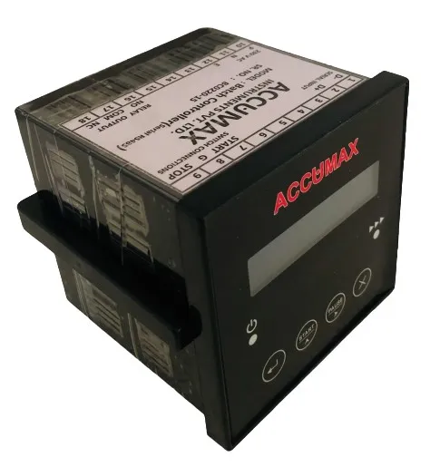
The Accumax Universal Flow Controller is a compact flow measurement and control unit used in laboratory and industrial settings to measure and read flow rates. It communicates with flow measuring devices over RS 485 and is set up from the front panel, where a display and push buttons are used to select modes, measurement units and timer.
How it works
Reads flow data from connected flow measuring devices over RS 485 serial communication and presents/controls it through a local display and push-button configuration; the page does not state the electrical input type or control output.
Features
-
Serial communication using RS485
Communicates with flow measuring devices over RS 485.
-
Five operating modes
Source says it 'can operate using 5 modes'. The five modes are never named anywhere on the page.
-
Flow controller / monitor functionality
Stated as both controlling and monitoring flow.
-
External push-button
Provision for an external push-button.
-
Password protection configuration
Configuration can be password protected for safer operation.
-
Display and push-button configuration
Front-panel selection of modes, measurement units and timer.
-
Completes batch even when a power interruption occurs
CAUTION: this bullet is in the product's own feature list but is copy-pasted batch-controller wording; confirm with Accumax that the UFC really has batch-resume behaviour before publishing it.
Operating modes
- Totalizer
- Monitor current flow and totalised volume.
- Batcher
- Dispense a set batch of liquid.
- Flow comparator
- Monitor two flow sensors (inlet vs outlet) and alarm on a reducing rate of recovery.
- Rate Switch
- Monitor current flow and alarm on crossing a preset threshold.
- Pulsar
- Trigger a task on completion of a preset volume — dosing applications.
- PID controller
- Control flow using a 4-20 mA output.
Technical specifications
31 values · 4 groups
These values are transcribed from the manufacturer's datasheet and are pending engineering sign-off. Confirm critical figures with Accumax before specifying.
| Operation and Modes | |
|---|---|
| Operating modes | Totalizer, Batcher, Flow comparator, Rate Switch, Pulsar, PID controller |
| Totalizer mode | To Monitor current flow and Totalized |
| Batcher mode | To make batch of liquid |
| Flow comparator mode | To monitor two flow sensor (Inlet Vs. Outlet) and Alarm on reducing rate of recovery |
| Rate Switch mode | To monitor current flow and Alarm on crossing preset threshold level |
| Pulsar mode | To operate specific task on completion of prefix volume. Dosing application. |
| PID controller mode | To control flow using 4-20mA |
| Selectable input units | L/S, L/M, L/H, KL/S, KL/M, KL/H, KG/S, KG/M, KG/H |
| Batch continuity | Completes batch even in power interrupt |
| Electrical | |
| Supply marking on terminal drawing | 230V AC |
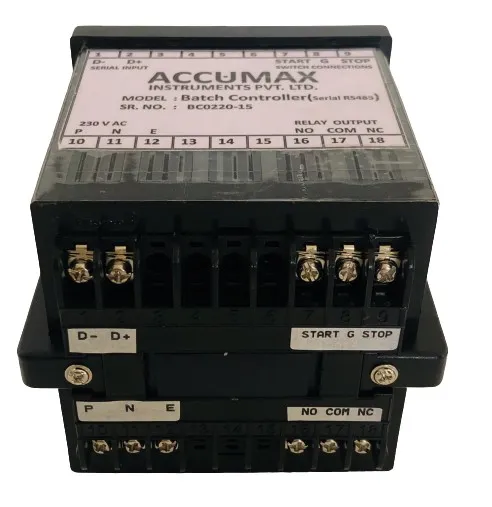
| Supply terminals | P: Phase, N: Neutral, E: Earth |
| Relay outputs | RELAY1 OUTPUT, RELAY2 OUTPUT |
| Relay output terminals | NO/NC/COM: Relay output terminals |
| Analogue output | 20mA O/P |
| Current output calibration points | COUNT FOR 4mA / COUNT FOR 20mA ("check 4 mA at output port of hardware", "check 20mA at output port of hardware") |
| External switch inputs | START: Push switch for start batch; STOP: Push switch for stop batch; G: common terminal for switch |
| Communication | |
| Serial communication | RS485 Serial communication |
| Modbus terminal | D+: RS485 MODBUS (+) |
| Communication parameters checked on fault | Device ID & Output Format |
| User Interface and Configuration | |
| Display | LCD Display |
| Front panel keys | Menu/Enter, Increment/Start, Shift/Stop, Cancel |
| External push button | External Push button provision |
| Entering setting mode | Press for 2 seconds for setting mode |
| Password — basic configuration | 1111 |
| Password — calibration setting | 2222 |
| Password — resetting | 9876 |
| Password protection | Password protected settings |
| Relay Energizer options | HIGHER THEN SET / LOWER THEN SET |
| Batch order options | INC / DEC |
| Rate Switch output selection | ONE / TWO |
| Settable parameters | Set Limit, Batch Order, Flow Recovery %, Output delay timer (Seconds), Set Cut off flow, Set higher flow, Set lower flow, Set Quantity, Relay on Time, Set Flow, Deviation |
Source: UFC1
9 further specification s are listed in the datasheet but not reproduced here
These labels appear in the datasheet, but the value beside them could not be read reliably from the document. Rather than print a figure we cannot stand behind, we have left them out — ask us and we will confirm them directly.
- Switch numbering in the Software Settings table — printed "Switch1 / Switch__ / Switch__ / Switch__"; only the first number survived
- Hardware version on the first connection drawing — printed "5.1 Version 1." with the minor digit lost (the second drawing reads "5.1 Version 1.0")
- Separator between the PID mode's current-loop endpoints — printed across a line break as "4" then "20mA"
- Terminal designation for the negative RS485 Modbus line — the label reads only ": RS485 MODBUS (" with the D- and the minus sign lost
- Deviation setting — printed "DEVIATION (+/" with the closing text and any range lost
- Supply voltage range — no supply-range spec row exists anywhere in this manual (only the "230V AC" nameplate caption)
- No environmental specification (operating temperature, humidity, IP rating) appears anywhere in this manual
- No enclosure dimensions, mounting, or weight appear anywhere in this manual
- No accuracy, flow range, or display resolution specification appears anywhere in this manual
Applications
- Food & Sugar Industries
- Pharmaceutical
- Textile
- Chemical
- Ceramic
- Paper Mills
- Industrial R.O.
- Water supply schemes
- STP Sewage treatment Plant
Frequently asked questions
How does the Universal Flow Controller connect to a flow meter?
It uses RS485 serial communication to communicate with flow measuring devices.
Can the configuration be locked so operators cannot change it?
Yes. It has password protection configuration in order to provide safer operation.
What can be set from the front panel?
It has a display and push-button configuration, making it easy to select different modes, measurement units and timer.
Which industries is it used in?
Food & sugar industries, pharmaceutical, textile, chemical, ceramic, paper mills, industrial R.O., water supply schemes and STP sewage treatment plants.
Gallery
Related products
Batch Controller
Programmable batch controller with relay output and external start/stop.
View details
Dosing Controller
Volume-based dosing controller that acts on a preset quantity, with RS 485 link and timer setup.
View details
Flow Comparator
Compares inlet vs outlet flow from two sensors and alarms on the inlet-to-outlet recovery rate.
View details
Need help specifying the right instrument?
Tell us the fluid, line size and accuracy you need. Our engineers will recommend a configuration and quote it.