Flow Meters
Digital Flow Meter With Telemetry System
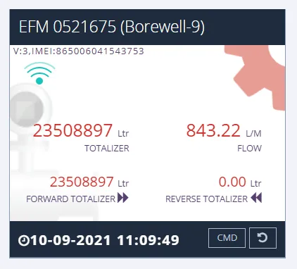
The Accumax Digital Flow Meter with Telemetry System is built to the latest Central Ground Water Authority (CGWA) guidelines and provides an IoT platform for water meters, allowing data acquisition from any remote location. Its cloud platform includes a real-time dashboard for viewing all analytical parameters required by CGWA, with tamper alerts and power-failure indication.
How it works
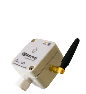
An electromagnetic flow meter is paired with a telemetry unit (inbuilt or external) that pushes readings over an IoT link to a cloud platform, where a real-time dashboard presents the analytical parameters required by CGWA and triggers email/SMS alerts on exceedance.
Features
-
Digital display for instantaneous flow
Local digital display shows instantaneous flow reading.
-
Built to CGWA guidelines
Follows CGWA, CGWB and CSWA/B guidelines.
-
IoT platform for remote access
Remotely accessible; suitable for data acquisition from any remote location.
-
Real-time cloud dashboard
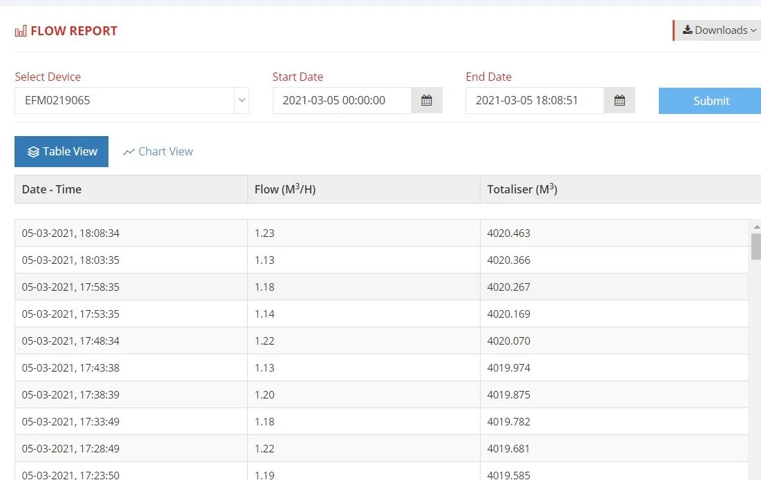
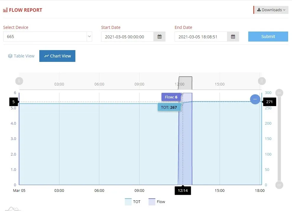
Cloud platform with a real-time dashboard for viewing all analytical parameters as per CGWA guidelines.
-
Email and SMS alerts
Alerts or notifications during parameter exceedance are received through email and SMS.
-
Tampering alert
Tampering alert is raised on the dashboard.
-
Power failure indication
Power failure indication is provided.
-
Data backup on request
Backup of data as per request.
-
No pressure drop
No pressure drop in flow.
-
Two variants
Electromagnetic flowmeter with inbuilt telemetry system, or electromagnetic flowmeter with external telemetry system.
-
Easy to install and user-friendly
Stated on the page as easy to install and user-friendly.
Technical specifications
47 values · 8 groups
These values are transcribed from the manufacturer's datasheet and are pending engineering sign-off. Confirm critical figures with Accumax before specifying.
| Metering and Metrology (as written in the CGWA guideline document) | |
|---|---|
| Metering Technology | Ultrasonic or Electromagnetic |
| Technology (flow meter section) | electromagnetic or ultrasonic |
| Turndown Ratio | 10 or above |
| Accuracy | better than ±2% for the operating flow range (from 10% to 100% of maximum flow rate) |
| Accuracy (lab testing section) | within ±2% in the operating range |
| Calibration laboratory | Testing or Calibration of meters shall be performed at ISO 17025:2017 accredited laboratory |
| Calibration points | At least 4 point calibration at 10%, 40%, 70% and 100% of maximum/rated flow |
| Magnetic field immunity | Meter performance shall not get affected by external magnetic field, as specified in ISO 4064 |
| Mounting plane | Meters must be able to retain their accuracy, when installed in either horizontal and/or vertical planes |
| Line Sizes and Flow Ranges | |
| DN40 | 0.25 lps to 5 lps |
| DN100 | 3 lps to 30 lps |
| DN150 | 13 lps to 130 lps |
| Other line sizes | Other line size available with ACCUMAX |
| Communication and Telemetry | |
| Communication type | LAN (for internet connectivity) or LoRa WAN and/or Cellular GPRS |
| Transmission frequency | The data shall be transmitted minimum 2 times in a day |
| Parameters transmitted to the secure cloud | Timestamp; Cumulative forward flow volume; Cumulative reverse flow volume; Cumulative Net volume; Cumulative pump working hours; Meter serial number; Device last calibration date; Borewell id (Provided by CGWA) |
| On-board data logging | Daily flow data with a timestamp, to be sent to the cloud via telemetry, for at least 2 years |
| Store-and-forward | In case the telemetry is non-functional because of power cut or weak cellular signals, the meter should be able to store the data and transmit to the cloud as soon as the telemetry system is live |
| Loss of communication indication | Indicated in the server within 48 hours |
| Encryption | The communication shall be encrypted to avoid tampering |
| Cloud service provider | Should be empaneled with The Ministry of Electronics and Information Technology (MeitY) |
| Electrical environment | The AMR/AMI should operate even in electrically noisy environments with electromagnetic interference and should function even in the presence of high voltage power lines |
| Configuration | The meter should be configurable either using the DTU or from the server |
| Power | |
| Power source | The meter shall be battery operated or UPS powered supply with provision of power OFF detection |
| Telemetry unit power | Battery operated or through external power supply; the metering data should be stored in the meter even if the telemetry system is off due to power failure |
| Battery life | At least 3 years with 2 transmissions per day; the battery shall be replaceable without any data loss. Not applicable in case of UPS Powered Supply |
| Battery monitoring | Battery usage has to be indicated at the server, with provision to replace batteries if required. Not applicable in case of UPS powered supply |
| Mechanical and Protection | |
| Manufacturing standard | Preferably manufactured as per ISO 4064:2014 Standards |
| Ingress protection | IP68 |
| Body material | Brass / Bronze / MS / SS / Engineering Plastic, compact enough to avoid tampering of meter |
| Indicator protective cover | Sturdy glass / PP / PC; straight reading type; the indicator cannot be removed from its place if the protective glass is broken |
| Totalizer material | Suitable material required to maintain IP68 protection class |
| Body markings | Make/Brand, Size/Nominal Dia., Sl. No./Year of Manufacture, Metrological specifications etc. |
| Sealing | The meter and telemetry system shall have proper mechanical and electronic sealing (through software) arrangement. Any attempt to open the meter or system enclosure should physically damage the tag |
| Alarms and Detection | |
| Detection capability | The meter should be capable to detect Leak, Zero (No) Flow, High Flow |
| Reverse flow | The meter should have the capability to detect and record reverse flow separately |
| Tamper alarm | The meters should report an alarm to the server as and when tampered |
| Real-time alarms | The system will communicate in real time for battery and tamper alarms |
| Timestamping | All Water Meter readings should be time stamped |
| Data Management Software | |
| Deployment | Cloud based with web portal access so that the user can view customer data through a browser; in addition, the software will be installed on a server placed in the Central Data Base / Control Room |
| Screens | Consumer, engineer and manager screens shall be available separately |
| Functions | Database backup/restore functions, real time data access, web-enabled, alerts to be provided through email/SMS to the user |
| Extensibility | Capability to add additional customer information and create customizable data fields |
| Accumax note on the software platform | ACCUMAX provides Cloud Computing Technology which is far better than this mentioned specifications |
| Installation | |
| Location | The meter shall be installed at the borewell pump discharge line before any branching |
| Bypass | There shall be no bypassing of pipe prior to the installed flow meter |
| Full flow | The installation of the meter shall ensure the pipe shall have full of water at all times. Sufficient upstream and downstream straight length shall be provided for the meter |
Source: ACCUMAX_CGWA_Guidelines
5 further specification s are listed in the datasheet but not reproduced here
These labels appear in the datasheet, but the value beside them could not be read reliably from the document. Rather than print a figure we cannot stand behind, we have left them out — ask us and we will confirm them directly.
- Tamper Proof — section label present with no value in the text layer
- Accuracy — Accumax's own figure; the sentence is cut off at "(Accumax provide accuracy better th"
- The content of Figure 1 (installation position of tamper proof flow meter with telemetry at groundwater abstraction structures)
- The content of the figure captioned "ACCUMAX Proposed System"
- Upstream/downstream straight-length figures — the document refers to Figure 1 rather than stating numbers in text
Applications
- Groundwater extraction monitoring under CGWA compliance
- Remote flow data acquisition from unmanned sites
- Real-time flow dashboards and reporting
- Exceedance alerting for regulated abstraction limits
Frequently asked questions
Does this meter comply with CGWA requirements?
Yes. It is offered as per the latest Central Ground Water Authority (CGWA) guidelines and follows CGWA, CGWB and CSWA/B guidelines, with a cloud dashboard showing all analytical parameters as per CGWA guidelines.
What variants are available?
Two variants: an electromagnetic flowmeter with an inbuilt telemetry system, and an electromagnetic flowmeter with an external telemetry system.
How are exceedance alerts delivered?
Alerts or notifications during parameter exceedance are received through email and SMS.
Can the system detect tampering or power loss?
Yes. A tampering alert is shown on the dashboard and power failure indication is provided.
Is historical data retained, and can it be exported?
The page states only that backup of data is available as per request.
Gallery
Related products
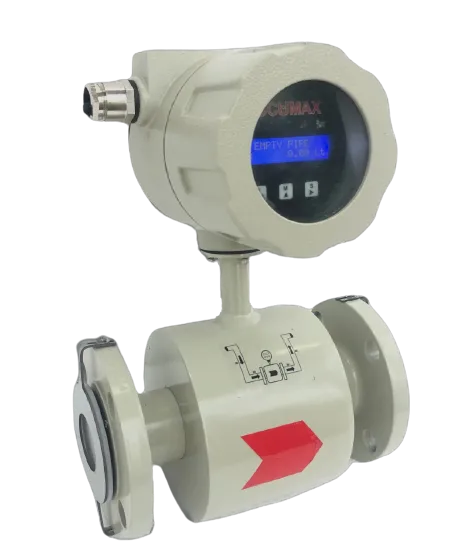
Electromagnetic Flow Meter
Full-bore electromagnetic meter for conductive liquids - no moving parts, no pressure drop, IP66 to IP68 build.
View details
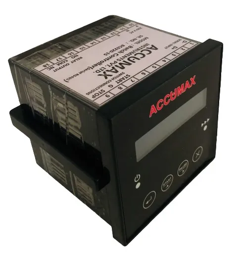
Paddle Wheel Flow Meter
Paddle wheel flow meter from 25 NB with 4-20 mA and RS485 Modbus output and six operating modes.
View details
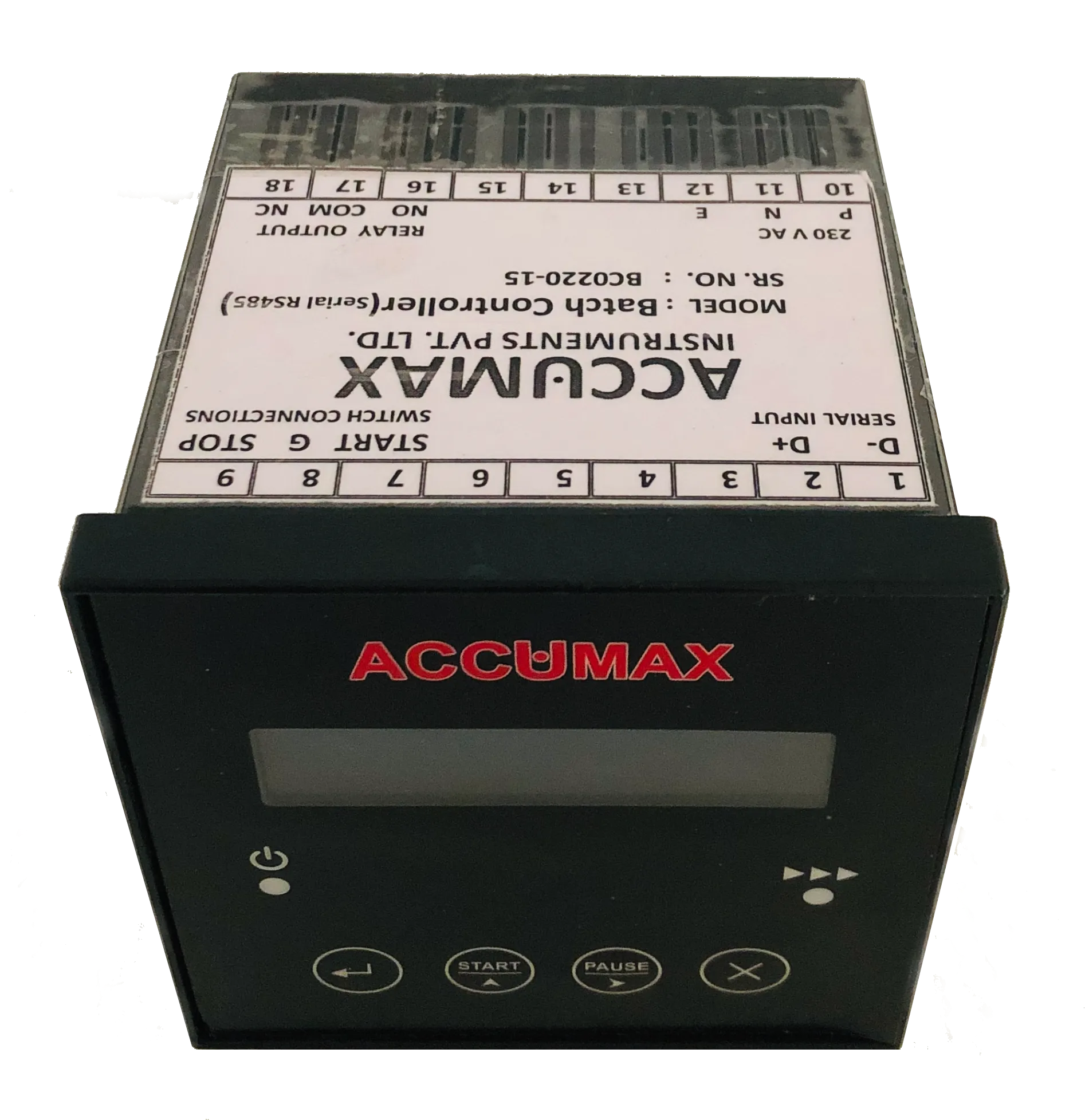
Turbine Flow Meter
Turbine flow meter with pulse output linear to flow - 1 in full bore plus insertion types up to 12 in.
View details
Need help specifying the right instrument?
Tell us the fluid, line size and accuracy you need. Our engineers will recommend a configuration and quote it.