Flow Meters
Electromagnetic Flow Meter
EFM-A-B-C-D-E-F-G-H-I-J-K
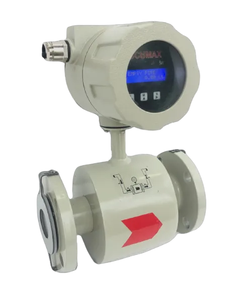
The Accumax Electromagnetic Flow Meter is a true volumetric meter for conductive liquids, operating on Faraday's law of electromagnetic induction. Provided the liquid maintains a certain minimum conductivity, the measurement is independent of temperature, viscosity, pressure and dissolved or undissolved solids.
Key specifications
- Line size
- 15 NB To 350 NB
- Flow range
- 0.2 m3/h to 1300 m3/h
- Output
- 4-20 mA / RS485 / Pulse
- Protection
- IP66 / IP67 / IP68
- Power supply
- 85 VAC-270 VAC, 50 Hz-60 Hz / 24 VDC
- Process pressure
- 20 bar or 20 kg/cm2
Key figures transcribed from the datasheet and pending engineering sign-off. Full specifications below.
How it works
Works on Faraday's Law of Electromagnetic Induction: the meter detects flow from the velocity of the conductive liquid passing through the measuring tube, and is calibrated in terms of volumetric flow rate.
Features
-
True volumetric measurement
Measures actual volume; as long as minimum conductivity is maintained, the reading is independent of temperature, viscosity, pressure and dissolved/undissolved solids.
-
Full-bore construction, no pressure drop
The unobstructed full-bore body means no pressure drop across the meter.
-
No moving parts
Maintenance-free construction because there are no moving parts to wear.
-
IP66 to IP68 construction
Rugged, robust construction. The datasheet lists protection class IP66, IP67 and IP68.
-
PTFE lining
Long-lasting PTFE lining maximizes the life of the meter.
-
Application-matched liner and electrode
Various types of liner and electrode are used as per application requirements.
-
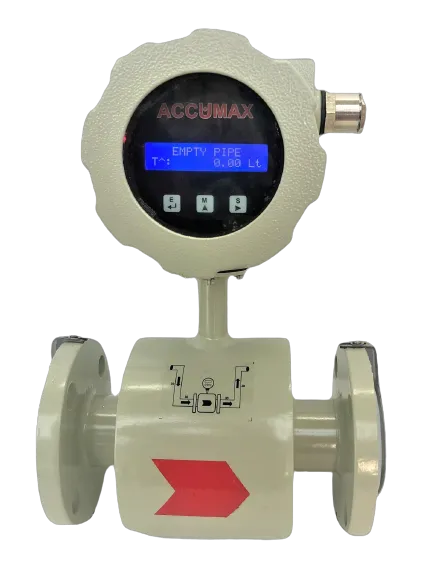
Empty pipe detection
Empty pipe detection is provided.
-
Customized designs
Customized designs are available as per requirement.
-
In-house R&D and calibration
Accumax has an in-house R&D centre and calibration setup as per industry standards.
Technical specifications
96 values · 12 groups
These values are transcribed from the manufacturer's datasheet and are pending engineering sign-off. Confirm critical figures with Accumax before specifying.
| Measurement | |
|---|---|
| Measurement Principle | Electromagnetic |
| Flow Measuring Range | 0.2 m3/h to 1300 m3/h |
| Measured Variables | Volume flow, mass flow |
| Media | Conductive Liquid |
| Electrical Conductivity of Liquid | >= 20 µS/cm for water |
| Flow Direction | Forward & Reverse (Reverse flow indicated with (-) sign before flow rate) |
| Flow direction setting (configurable) | Forward, Reverse or Bidirection |
| Low Flow Cut-Off | User Configurable - 0 to 10% |
| Damping Time | User Configurable |
| Empty pipe detection | Empty pipe alert |
| Empty Pipe Status setting | Option available: disable, Enable |
| Excitation Frequency | Available option: 6.25, 3.125 |
| Calibration Range | Wet calibrated at IEC/ISO/EN17025 accredited calibration laboratory |
| Totalizers | Totalizer (positive), totalizer (negative) and delta totalizer (^) = (positive totalizer - negative totalizer) |
| Flow Range by Line Size | |
| 15 NB — Min flow | 0.2m3/h |
| 20 NB — Min flow | 0.3m3/h |
| 25 NB — Min flow | 0.45m3/h |
| 40 NB — Min / Max flow | 1.1 / 22m3/h |
| 50 NB — Min / Max flow | 1.8 / 36m3/h |
| 65 NB — Max flow | 60m3/h |
| 80 NB — Min / Max flow | 4.5 / 90m3/h |
| 100 NB — Min / Max flow | 6.05 / 121m3/h |
| 125 NB — Min / Max flow | 10 / 200m3/h |
| 150 NB — Min / Max flow | 15.9 / 318m3/h |
| 200 NB — Min / Max flow | 22.5 / 450m3/h |
| 250 NB — Min / Max flow | 30 / 600m3/h |
| 300 NB — Min / Max flow | 42.5 / 850m3/h |
| 350 NB — Min / Max flow | 65 / 1300m3/h |
| Note printed on the chart | MIN FLOW (m3/h) (in general, 5% of Max Flow) |
| Electrical | |
| Power Supply | 85 VAC-270 VAC, 50 Hz-60 Hz / 24 VDC |
| Output | 4-20 mA / RS485 / Pulse |
| Power Consumption | <10 VA |
| Isolation | 1.4 kV between Input, Output & Power Supply |
| Alarm Output | Low & High Flow Alarm (Open Drain) |
| Alarm output load | Max 50 mA DC (Buzzer, LED, Relay) |
| Pulse output | Maximum load is 80 mA, pulse width is 10 mS |
| 4-20 mA loop source | Two source options — Internal (IS, default) & External (ES), jumper selected |
| Output options (customisation) | Multiple output options are available, including 4-20 mA, pulse, and RS485 |
| Communication (RS485 / Modbus) | |
| Baud rate | 2400, 4800, 9600, 19200, 38400 |
| Parity | NONE, ODD, EVEN |
| Stop bit | ONE, TWO |
| Device ID | 010 (as shown on the settings screen) |
| Modbus output format | Float, Long Integer, Decimal, Integer |
| Display and Configuration | |
| Display | Standard 16*2 LCD |
| Display Resolution / Smallest Division | Flowrate: 0.01 L/min or 0.01 m3/h; Totalizer: 10 digits Totalizer |
| Configuration Data | 3 Tactile Membrane Keys for Data Configuration |
| Units of Measurement | L, m3, kg, kL (User Configurable) |
| Unit list (converter menu) | L/S, L/M, L/H, KL/S, KL/M, KL/H, KG/S, KG/M, KG/H |
| Flow Totalizer Reset | Totalizer Reset Facility by Password Protection |
| Security | Password Protection for Configuration of Data |
| Menu passwords | 1111 Basic configuration, 2222 Calibration setting, 3333 Modbus setting, 5555 Pulse Output Setting, 6666 Set Zero Flow |
| Pulse output units | L/P, m3/P, Kl/P |
| Mechanical | |
| Line Size Options | 15 NB To 350 NB |
| Types Available | Integral / Remote (Up to 10 m Cable Length) |
| Protection Class | IP66 / IP67 / IP68 |
| Liner | PTFE (Teflon), Rubber (Neoprene) |
| Lining Material (customisation options) | PTFE, hard rubber, polyurethane |
| Process Connection | Flange End |
| Flange Material | MS #150 / SS304 #150 / SS316 #150 |
| Flow Tube | SS304 / SS316 |
| Electrode Material | SS316L / Hastelloy C22 |
| Sensor Housing Material | Carbon Steel with protective Varnish |
| Transmitter Housing Material | AlSi10Mg, coated |
| Process Pressure | 20 bar or 20 kg/cm2 |
| Grounding | Built-in grounding electrode (3rd electrode); optional grounding rings at both ends on plastic pipelines and lined metal pipes (grounding rings are not included in the delivery) |
| Name plate and warning inscription | Name-cum-warning inscription plate and rating plate made of Brass/SS, permanently fixed on the cover of enclosure by hammer driven rivets leaving min. 3 mm material thickness around the rivets; inscription reads DO NOT OPEN WHEN ENERGIZED |
| Environmental | |
| Operating Temperature Range (Medium Temperature Range) | -10 (0) °C to +200 °C (Remote display); PTFE: up to 230 °C; Rubber: up to 85 °C |
| Relative Humidity | 0-95% |
| Installation Requirements | |
| T-connection upstream distance | 10 DN distance upstream the flow meter |
| Gate valve clearance | Keep 5 meters between the axis of the flow meter and the axis of the gate valve located downstream |
| Converter position (horizontal pipes) | The converter (or the junction box in the separate version) must be placed on the upper part |
| Recommended orientation | Vertical / inclined pipe with upward flow direction; avoid installation in vertical pipes with free outlet |
| Pump position | Always install the sensor downstream the pump and NEVER upstream to avoid vacuum |
| Optional Functions | |
| Batching Facility | Available |
| Data Logging | Available |
| Telemetry | Available |
| Telemetry Variant (Electromagnetic Flow Meter with Telemetry) | |
| Base specification | All specs as mentioned above for Non-Telemetry, plus the below |
| Connectivity | Compatible with GPRS/GPS |
| Cloud Application — Dashboard | Compatible on PC / Mobile Phone / iPad |
| Cloud Application — Features | Reports, Real-Time Data Access, Multi-User Login, Group Allocation |
| Alerts | Temper Alert and Power Failure Alert |
| Dashboard View | Tabular view, Chart view |
| Subscription | Yearly via Payment Gateways |
| Ordering Code (EFM-A-B-C-D-E-F-G-H-I-J-K) | |
| A — Line Size | NB |
| B — Lining Material | PTFE, Rubber |
| C — Electrode Material | SS316L, Hastelloy C |
| D — Flange and Coil Housing | MS, SS |
| E — Class of Flange | Class 150, 300, 600 |
| F — Special Paint | No (Siemens Grey), Mention Color |
| G — Output 4-20 mA | No: 0, Yes: 1 |
| H — Output RS485 (MODBUS) | No: 0, Yes: 1 |
| I — Display | Integrated: I, Remote: R |
| J — Pulse Output | No: 0, Yes: 1 (Pulse 0 for Telemetry) |
| K — Supply Voltage | 220 VAC, 110 VAC, 24 VDC |
| Example ordering code | EFM-50-PTFE-SS316L-MS-150-NO-1-1-I-0-220V |
| Warranty | |
| Warranty | 1 Year |
Sources: EFM_Datasheet_150923, EMF_MANUAL_V2
12 further specification s are listed in the datasheet but not reproduced here
These labels appear in the datasheet, but the value beside them could not be read reliably from the document. Rather than print a figure we cannot stand behind, we have left them out — ask us and we will confirm them directly.
- Accuracy (or Max. Measurement error) — label present in the technical specification table, value cell lost
- Repeatability — label present in the technical specification table, value cell lost
- Ambient Temperature Range — label present in the technical specification table, value cell lost
- Configuration functions/parameters — label present in the transmitter-unit table, value cell lost
- PIPE ID column of the LINE SIZE / MINIMUM AND MAXIMUM FLOW RATE CHART — every cell lost
- MAX FLOW column header of the LINE SIZE / MINIMUM AND MAXIMUM FLOW RATE CHART
- MAX FLOW for line sizes 15, 20 and 25 NB
- MIN FLOW for line size 65 NB
- Other Approvals — the first approval listed (the line opens with a stray comma before ISO 4064:2014)
- Maximum external loop-supply voltage for the 4-20 mA input (EMF_MANUAL_V2 reads 'In case of external source voltage should not above 2_ DC.' — the figure is cut off)
- Empty pipe upper and lower threshold default counts (EMF_MANUAL_V2)
- Pipe ID column of the Max Flow table in EMF_MANUAL_V2, and the Max Flow value for 25 NB
Applications
- Measuring acidic chemicals
- Waste water measurement
- Warm / hot water measurement
- Water supply projects
- Sewage treatment plant (STP) flow measurement
- Effluent treatment plant (ETP) flow measurement
Certification
-
Flameproof and potentially-explosive-atmosphere construction standards are named in the datasheet's Key Features. No certificate or approval number is shown.
"Flameproof (IS/IEC 60079-1:2007)/ Weatherproof/ Can function in Potentially Explosive Atmosphere (IS/IEC 60079-0: 2004)"
Source: EFM_Datasheet_150923
-
Listed under the datasheet's 'Other Approvals' row. The line begins with a stray comma, so at least one further approval was lost by the text layer.
", ISO 4064:2014"
Source: EFM_Datasheet_150923
-
Listed under 'Meteorological Approvals and Certificates' (spelled so in the PDF). Describes where calibration is performed; no certificate number is shown.
"Calibration performed on accredited calibration facilities (acc. To ISO/IEC 17025)"
Source: EFM_Datasheet_150923
-
Calibration Range row of the technical specification table.
"Wet calibrated at IEC/ISO/EN17025 accredited calibration laboratory"
Source: EFM_Datasheet_150923
Frequently asked questions
What liquids can the Accumax electromagnetic flow meter measure?
It measures conductive liquids found in industrial processes, including acidic chemicals, waste water and warm/hot water. The liquid must maintain a certain minimum conductivity for the measurement to work.
Does the meter cause a pressure drop in the line?
No. The meter uses a full-bore construction, so there is no pressure drop.
Is it affected by fluid temperature, viscosity or suspended solids?
No. As long as the minimum conductivity is maintained, the flow measurement is independent of temperature, viscosity, pressure and dissolved or undissolved solids.
Can it detect an empty pipe?
Yes, empty pipe detection is provided.
What is the ingress protection rating?
The datasheet lists protection class IP66, IP67 and IP68. Confirm which rating applies to the build you are ordering.
Which electrode materials can be supplied?
The specification table lists SS316L and Hastelloy C22, selected to suit the process fluid. Confirm the grade against your fluid before ordering.
Gallery
Related products
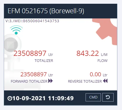
Digital Flow Meter With Telemetry System
Digital flow meter built to CGWA guidelines, with IoT telemetry, cloud dashboard and email/SMS exceedance alerts.
View details
Paddle Wheel Flow Meter
Paddle wheel flow meter from 25 NB with 4-20 mA and RS485 Modbus output and six operating modes.
View details
Turbine Flow Meter
Turbine flow meter with pulse output linear to flow - 1 in full bore plus insertion types up to 12 in.
View details
Need help specifying the right instrument?
Tell us the fluid, line size and accuracy you need. Our engineers will recommend a configuration and quote it.