Flow Meters
Turbine Flow Meter
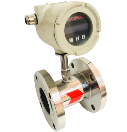
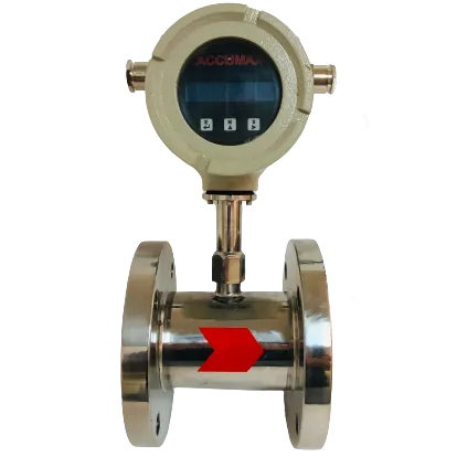
The Accumax Turbine Flow Meter measures volumetric total flow and flow rate using a rotor whose angular velocity is directly proportional to fluid velocity, with the signal picked up by an electrical pick-off on the meter body.
Key specifications
- Line size
- from 15 NB
- Accuracy
- ±1% FS
- Output
- 4-20 mA and RS485
- Process pressure
- Up to 30 kg/cm2
- Media
- Liquid
Key figures transcribed from the datasheet and pending engineering sign-off. Full specifications below.
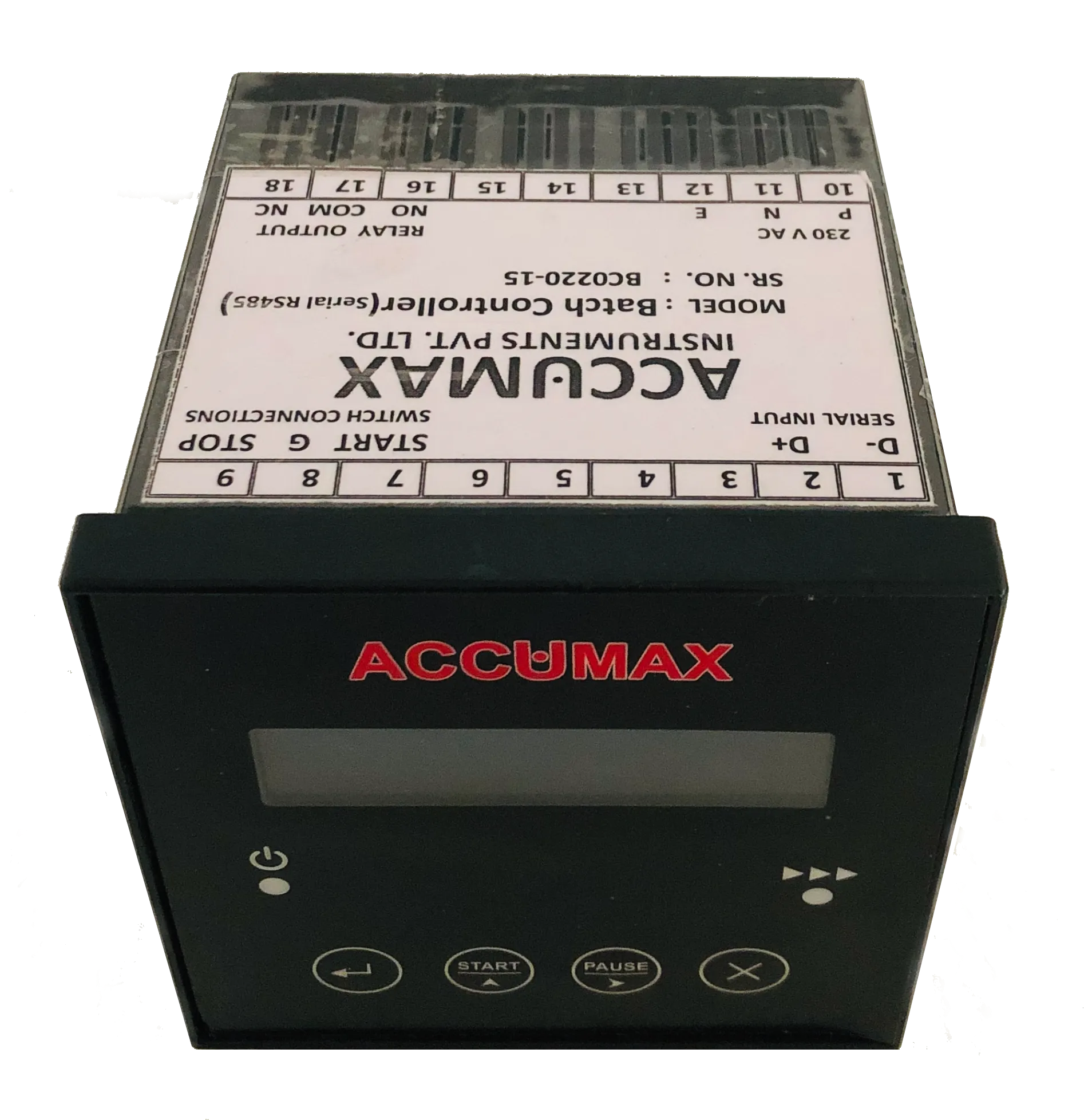
How it works
Fluid flowing through the meter impinges on turbine blades free to rotate about an axis along the centre line of the housing. The angular (rotational) velocity of the rotor is directly proportional to the fluid velocity, and the resulting signal is taken by an electrical pick-off mounted on the flow meter body.
Features
-
Individually calibrated, K factor marked
Each fitting is individually calibrated and marked with its K factor in ml/pulse.
-
Ceramic ball bearing
Ceramic ball bearing for superior low flow performance.
-
High-level 5 VDC signal
High level (5 VDC) signal can be run up to 100 ft without a transmitter.
-
Linear pulse output
Pulse output is linear to the flow rate, with high-frequency pulse resolution to account for minute increments of flow.
-
Full bore and insertion models
1 in full bore turbine type; insertion type available for 1.5, 2, 2.5, 3, 4, 6, 8 and 12 in line sizes.
-
Five operating modes
Indicator & Totalizer, Batcher, Flow Comparator, Rate Switch Mode and Pulser.
-
Batcher with halt and reject
Relay energizes on start and remains energized until a fixed quantity of liquid passes the sensor; the batcher has halt and reject batch functions.
-
Flow comparator mode
Two sensors on permeate and reject lines; the meter displays both flow rates, calculates percentage recovery and alarms on reducing recovery.
-
Rate switch mode
Relay energizes whenever actual flow falls below or rises above the set value, with LOW/HIGH FLOW RATE shown on the display - suited to flow interlock and chemical dosing.
-
Pulser mode
Triggers a task on completion of a preset volume; can be configured to any metering or dosing pump.
-
Self-locating insertion probe
Fitting is automatic since the probe is set at the correct depth and orientation.
-
PVC tee adaptors available
Insertion type sensor is also available with solvent cementable adaptors for PVC tees at extra cost.
-
Recommended straight run
For best results, provide a straight run of 10D upstream and 5D downstream.
Technical specifications
49 values · 9 groups
These values are transcribed from the manufacturer's datasheet and are pending engineering sign-off. Confirm critical figures with Accumax before specifying.
| Measurement | |
|---|---|
| Indication | Flow rate, Totalizer |
| Size | 15 To 100 NB |
| Line size (front page claim) | Line Size from 15 NB |
| Media | Liquid |
| Service | Oil, Solvent, Diesel, Chemical |
| Accuracy | ±1% FS |
| Density of liquid | 700 - 1300 kg/m3 |
| Flow Range by Pipe Size | |
| Pipe sizes listed in the flow range table | 15, 25, 40, 50, 65, 80, 100NB |
| Min. Flow, in table order for 15 / 25 / 40 / 50 / 65 / 80 / 100 NB | 0.2 / 0.8 / 1.9 / 3.5 / 5.8 / 7.5 / 14m3/h |
| Max. Flow — only 5 of the 7 cells survived the text layer, listed in the order printed | 19 / 35 / 58 / 75 / 140m3/h |
| Electrical and Output | |
| Output | 4-20 mA and RS485 |
| Serial output | RS485 Modbus output |
| GSM interface | GSM Interface compatible (Optional) |
| Sensor supply at controller terminals 3 & 4 | 12 - 16 V DC |
| Sensor cable cores | Red, Black & Green |
| Communication (RS485 / Modbus) | |
| Baud rate | 2400, 4800, 9600, 19200, 38400 |
| Parity | NONE, ODD, EVEN |
| Stop bit | ONE, TWO |
| Device ID | 010 (as shown on the settings screen) |
| Modbus output format | Float, Long Integer, Decimal, Integer |
| Display and Configuration | |
| Display | 2 line LCD (16*2) |
| Type | Integral / Remote |
| Enclosure | Robust Design & Available in two enclosure design |
| Keys | Switch 1 Menu/Enter, Switch 2 Increment/Start, Switch 3 Shift/Stop, Switch 4 Cancel |
| Menu passwords | 1111 Basic configuration, 2222 Calibration setting, 3333 Modbus setting, 9876 Resetting configuration |
| Selectable units | L/S, L/M, L/H, KL/S, KL/M, KL/H, KG/S, KG/M, KG/H, Ml/S, Ml/M, Ml/H |
| Calibration input | Set Input Flow entered as Litre per Pulse (L/P) |
| Second totalizer reset | Reset To2 by pressing and holding the menu key about 200 ms |
| Flow comparator settings | Flow Recovery %, Output Fall timer (Seconds), Relay Energizer (Higher than set / Lower than set), Set Output Flow |
| Batcher settings | Set Limit, Batch Order (INC / DEC) |
| Rate switch settings | Set Cut-off flow, Relay Energizer (Higher than set / Lower than set) |
| Pulsar settings | Set Quantity, Relay On Time (seconds) |
| Mechanical | |
| MOC | SS 304 / SS 316 - As per application |
| Rotor | SS 410 |
| Connection | Flanged / TC end available |
| Pressure | Up to 30 kg/cm2 |
| Environmental | |
| Temperature | Up to 70 deg. Celsius |
| Operating Modes | |
| Totalizer | To Monitor current flow and Totalized |
| Batcher | To make batch of liquid |
| Flow comparator | To monitor two flow sensor (Inlet Vs. Outlet) and Alarm on reducing rate of recovery |
| Rate Switch | To monitor current flow and Alarm on crossing preset threshold level |
| Pulsar | To operate specific task on completion of prefix volume. E.g. Dosing application |
| Dual Totalizer | It's a 2nd totalizer. It can be used regardless of totalizer 1 settings |
| Installation Requirements | |
| T-connection upstream distance | 10 DN distance upstream the flow meter |
| Gate valve clearance | Keep 5 meters between the axis of the flow meter and the axis of the gate valve located downstream |
| Recommended orientation | Vertical / inclined pipe with upward flow direction; avoid installation in vertical pipes with free outlet |
| Pump position | Always install the sensor downstream the pump and NEVER upstream to avoid vacuum |
| Strainer | Prevent solid particles entering the sensor; fix a strainer before the sensor / flow tube |
| Maintenance | It is mandatory to clean sensor over periodically to ensure best performance |
Sources: TURBINE_BROCHURE, DFM_ROUND_MANUAL
5 further specification s are listed in the datasheet but not reproduced here
These labels appear in the datasheet, but the value beside them could not be read reliably from the document. Rather than print a figure we cannot stand behind, we have left them out — ask us and we will confirm them directly.
- Max. Flow for two of the seven pipe sizes in the brochure's Flow Range table — only 5 of the 7 cells survived the text layer
- Accuracy value on the brochure's first spec-table rendering (the row reads "Accuracy" then "FS"); recovered from the second rendering in the same PDF
- Enclosure dimensions and IP rating — no text value anywhere in the three PDFs
- K factor value — the page copy mentions individual calibration marked with a K factor (ml/pulse) but no K factor figure appears in any PDF
- Sensor bearing, straight-run and insertion-type details — none of these appear in the PDF text; they exist only in the web page copy
Applications
- Volumetric total flow and flow rate measurement
- Measurement and control
- Batching applications
- Flow rate comparison (inlet vs outlet) and RO recovery monitoring
- Dosing applications
- Flow interlock and chemical dosing via rate switch
Frequently asked questions
What line sizes does the Accumax turbine flow meter cover?
A 1 in full bore turbine type, plus an insertion type available for 1.5, 2, 2.5, 3, 4, 6, 8 and 12 in line sizes.
How far can the sensor be mounted from the display without a transmitter?
The high level (5 VDC) signal can be run up to 100 ft without a transmitter.
What straight run does the meter need?
For best results Accumax recommends a straight run of 10D on the upstream side and 5D on the downstream side.
Is each meter calibrated before dispatch?
Yes. Each fitting is individually calibrated and marked with its K factor in ml/pulse.
What output does the meter provide?
A pulse output that is linear to the flow rate, with high-frequency pulse resolution; the high-level signal is 5 VDC.
What operating modes are available?
Five: Indicator & Totalizer, Batcher (with halt and reject batch), Flow Comparator (two sensors with percentage recovery and low-recovery alarm), Rate Switch Mode (relay on low/high flow) and Pulser (triggers on a preset volume).
Gallery
Related products
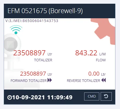
Digital Flow Meter With Telemetry System
Digital flow meter built to CGWA guidelines, with IoT telemetry, cloud dashboard and email/SMS exceedance alerts.
View details
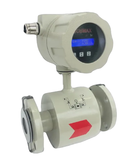
Electromagnetic Flow Meter
Full-bore electromagnetic meter for conductive liquids - no moving parts, no pressure drop, IP66 to IP68 build.
View details
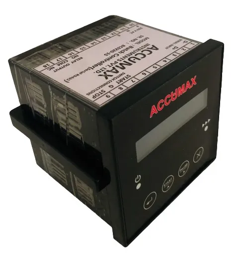
Paddle Wheel Flow Meter
Paddle wheel flow meter from 25 NB with 4-20 mA and RS485 Modbus output and six operating modes.
View details
Need help specifying the right instrument?
Tell us the fluid, line size and accuracy you need. Our engineers will recommend a configuration and quote it.